Why CRN Registration Matters: Key Benefits for Pressure Equipment Manufacturers
November 20, 2025
ASME UHA-51 Impact Testing: Avoid Delays, Stay Compliant
February 11, 2026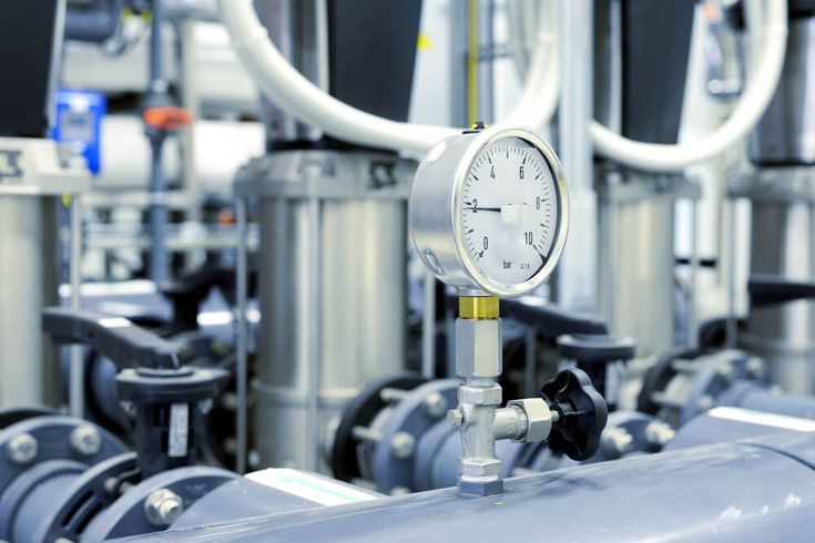
On This Page
ASME Section VII Vessel Pressure Testing Standards
Confused by ‘Section VII’? These tests live in ASME Section VIII (American Society of Mechanical Engineers)—UG‑99 hydro, UG‑100 pneumatic, UG‑101 proof—and we turn that into a plain‑English, code‑accurate guide for Canadian projects so you pass first time.

Design Meets Reality: The Make‑or‑Break Pressure Test
If “Section VII” keeps popping up, it’s because this is the moment everything gets real. The crew’s in PPE (personal protective equipment), the inspector’s watching, and your turnover date is riding on one hold at pressure. One missed vent or bad gasket can turn a 90‑minute test into a two‑week slip. The pressure test proves design math and workmanship—and most failures trace to setup or paperwork, not the steel. We prevent that.
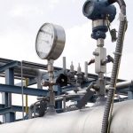
Cost and safety swing with the method. Hydrostatic means weight, spill risk, and dry‑out; pneumatic stores energy that demands exclusion zones and remote monitoring. The pass/fail difference is discipline: current gauge calibrations (usually 12 months), a set PRV (pressure relief valve) just above test pressure, matching CRN (Canadian Registration Number) on every record, and a clean, traceable procedure. Nail the bundle, and you keep schedule and people safe.
So what does the Code actually require, line by line? Let’s translate ASME Section VIII—UG‑99 hydro, UG‑100 pneumatic, UG‑101 proof—and retire the Section VII myth once and for all.
ASME Section VIII governs vessel tests—Section VII does not. Here’s why
You asked what the Code actually requires—here’s the plain-English map. Pressure-vessel testing lives in ASME Section VIII, Division 1: UG-99 (hydrostatic test, with water), UG-100 (pneumatic test, with gas), and UG-101 (proof/burst testing to establish maximum allowable working pressure). Section VII is different: it’s the Care of Power Boilers (operating guidance), not construction or test rules for vessels. Example: a shop hydro under UG-99 is the default; gas per UG-100 needs added controls.
Most vessels you build or buy use Section VIII, Division 1; Divisions 2 and 3 have different detail and acceptance paths, so confirm your scope on the nameplate and data report. UG-99 sets hydro pressure and visual exam criteria; UG-100 permits gas only when hydro is impractical and risk controls are in place. UG-101 fits novel geometries needing proof. Again, Section VII covers boiler operation practices—not vessel construction tests—so don’t cite it in your procedure.
In Canada, your procedures and records should reference these ASME clauses and tie to the CRN (Canadian Registration Number). We align ASME VIII with provincial rules and Boilers and Pressure Vessels CRN registration so test pressure, temperature, and acceptance criteria match code and jurisdiction, avoiding back-and-forth.
Where vessel pressure tests go off the rails
From our audits, the same misses cause delays and rework. Spot them early, and you’ll protect safety and schedule. Here’s what we check every time.
- Misapplied LSR: Using the wrong lowest stress ratio (S_test/S_design, test-to-design allowable stress) across materials or temperatures inflates pressure—recalculate and adjust temperature.
- Ignoring MDMT window: Testing below MDMT (minimum design metal temperature) +30°F or above 120°F invites brittle fracture—control ambient, preheat, or reschedule.
- Bolting oversight: At test temperature, bolt stress must not exceed 90% of yield—use lower gasket seating stress, re-torque, or temporary test bolts.
- Pneumatic by convenience: Don’t choose gas unless UG-100(a) criteria are met and pre-examinations per UW-50 confirm readiness; document risk controls.
- Paperwork gaps: Missing gauge calibrations, incomplete ramp/hold records, or broken weld/NDE (non-destructive examination) traceability will halt acceptance—build a binder before test day.
Why Canadian approvals punish sloppy testing and weak docs
TSSA in Ontario (Technical Standards and Safety Authority) and ABSA in Alberta (Alberta Boilers Safety Association) move faster when your package is clean: correct test method, controlled temperature, and traceable calibrations. That quality signals low risk and earns inspection throughput. We also coordinate vessel testing with related pressure piping testing so hold points don’t collide. Result: fewer re-tests, fewer site visits, and less standby time waiting for witness. That’s how you keep pressure, temperature, and documentation marching together.
The schedule hit is real: a failed test can push witness dates, idle crews, and force rework on insulation, drying, or confined space entries. Costs climb fast—rental nitrogen, temporary heat, desiccant, truck demurrage, and overtime for after-hours access. Coordination matters because vessel sign-off often gates piping hydro, reinstatement, and turnover. When your test method, temperature controls, and records align on day one, regulators spend minutes approving instead of hours questioning. Next, we’ll give you the step-by-step decision framework to choose UG-99, UG-100, or UG-101 with confidence.
Select and Execute: UG‑99 vs UG‑100 vs UG‑101, Step‑by‑Step
You wanted the step-by-step framework—here it is. Follow these seven code‑referenced steps to pick your test and pressure using ASME VIII UG‑99/UG‑100/UG‑101, MAWP and MDMT—e.g., 300 psig MAWP ×1.3×0.95 ≈ 370 psig hydro.
- Step 1: Confirm scope: Record Division, materials, MAWP (max allowable working pressure), MDMT (min design metal temperature), joint category, UHA (high alloy), UCS (carbon/low‑alloy), UNF (nonferrous), plus nameplate/CRN.
- Step 2: Choose default test: Select hydrostatic per UG‑99. Use UG‑100(a) pneumatic only if hydro is impractical (cleanliness, weight, trapped fluid) and document risk controls with owner/inspector approval.
- Step 3: Compute LSR: LSR = S_test/S_design (allowable at test temp ÷ at design). Use the lowest across materials; exclude bolts unless they may exceed 90% yield.
- Step 4: Set test pressure: Hydro = 1.3×MAWP×LSR; pneumatic = 1.1×MAWP×LSR. Verify limits: flange class, gaskets, nameplate, nozzles, and instruments must tolerate test pressure and temperature.
- Step 5: Control temperature: Keep vessel and test medium between MDMT +30°F and 120°F; keep shell and contents at essentially the same temperature to avoid local brittle zones.
- Step 6: Pre-test examinations: Complete visual/NDE (non‑destructive examination) and any UW‑50 prechecks; confirm calibrated gauges, chart recorders, and PRV (pressure relief valve) setpoint above test pressure with certification.
- Step 7: Record and reduce: Hold at test pressure, then reduce to inspection pressure (÷1.3 hydro; ÷1.1 pneumatic). Perform leak checks, capture pressure/temperature/time data, and obtain inspector signoffs.
UG-99 Hydro: Run the test inspectors expect
You’re set to hold, then drop to inspection pressure (divide by 1.3)—now let’s run UG‑99 the right way. Choose clean water or compatible glycol, keep temperature safely above MDMT (minimum design metal temperature), and fill from low with vents open high to de‑aerate. Use two calibrated gauges (different ranges) plus a recorder for redundancy. Pressurize in stages—25%, 50%, 75%, 100%—stabilize, then hold at test pressure. Example: 300 psig MAWP (maximum allowable working pressure) with LSR 0.95 → ~370 psig test; inspect at ~285 psig after reduction. Follow our ASME hydrostatic pressure testing sequence to capture clean readings and make inspection smooth.
Plan the back end before you pump: set drain points, route to totes or approved sewer, and add inhibitors if carbon steel will sit wet. Place one gauge on the vessel, one on the pump header, and mount a thermowell on the shell so water and metal temperatures track together. Keep barricades up during hold, then depressurize slowly, reduce to test/1.3 for visual inspection, and mark any seeps. Dry fully—air knives, desiccant, or low‑temp heat—and document disposal volumes and water chemistry. For reference, LSR (allowable stress ratio S_test/S_design) and MDMT controls must be noted on the record; that’s what the reviewer looks for.
💡
Formula
Minimum Hydrostatic Test Pressure = 1.3 × MAWP × LSR
UG-100 Pneumatic: Safety-First, Inspector-Ready Execution
You set hydro at 1.3×MAWP×LSR; with gas, UG‑100 changes the risk and the steps. We start with UW‑50 pre‑exams (weld examinations before testing) and a JSA/HAZID (job safety analysis/hazard identification) that quantifies stored energy and defines exclusion zones. We use nitrogen (inert, clean, dry) or clean dry air. We size and certify a PRV (pressure relief valve) just above test pressure, and verify capacity for the vessel volume. Ramp in small steps—25%, 50%, 75%, 90%, 100%—pausing to check for leaks. Stabilize temperature, hold, then reduce to inspection pressure (divide by 1.1) for soap‑solution checks. Example: MAWP (maximum allowable working pressure) 300 psig with LSR (allowable stress ratio) 0.95 → 1.1×300×0.95 ≈ 313 psig; inspect ≈ 285 psig.
Now, we make the field safe and simple so you can run with confidence. We set barricades and red‑zone signage; you keep non‑essential people out. We use remote monitoring—camera on gauges, wireless temperature, and a control valve outside the zone. We apply LOTO (lockout/tag‑out isolation) on feeds, vents, and instrument air; we tag the PRV and test manifold. Communications plan: one test director, radio checks, and countdown calls at each ramp. Abort criteria upfront (unexpected pressure spike, leak sound, or temperature drift) with documented stop/depressurize steps. Capture the pressure/temperature chart, PRV setpoint certs, gauge calibrations, and JSA signoffs. Inspectors move fast when the paperwork is clean. Next, we’ll unpack the math in a full worked example.
⚠️
Formula
Minimum Pneumatic Test Pressure = 1.1 × MAWP × LSR
Worked example: how LSR sets pressure
We just said pneumatic test pressure equals 1.1 × MAWP × LSR (maximum allowable working pressure × lowest stress ratio S_test/S_design). Let’s put numbers on it. Say your SA‑516‑70 carbon steel vessel is MAWP 300 psig, design 400°F, test at 90°F. If ASME tables give S_design = 20.0 ksi and S_test = 21.5 ksi, LSR = 21.5/20.0 = 1.075. Hydro (UG‑99): 1.3×300×1.075 ≈ 419 psig (round to 420). Pneumatic (UG‑100): 1.1×300×1.075 ≈ 355 psig. Bolt exception: we don’t use bolt allowables in LSR, but we must show stud bolt stress stays under 90% of yield at test pressure; if not, use temporary higher‑class bolts or lower gasket seating load.
Now flip temperature and material to see the swing. A 304L stainless vessel, MAWP 300 psig, design 200°F, winter test at 40°F. If S_design = 18.0 ksi and S_test = 16.0 ksi (cooler allowable lower for this alloy in the tables), LSR = 16.0/18.0 = 0.89. Hydro (UG‑99): 1.3×300×0.89 ≈ 347 psig. Pneumatic (UG‑100): 1.1×300×0.89 ≈ 294 psig. Check MDMT (minimum design metal temperature): keep test temperature at least MDMT + 30°F, and confirm flange/gasket ratings still clear the adjusted pressure. Next, we’ll stack hydro vs pneumatic side‑by‑side so you can choose fast.
Hydro vs Pneumatic: a quick, code-accurate comparison
Here’s the side‑by‑side we promised. We define MAWP (maximum working pressure), LSR (allowable stress ratio), MDMT (minimum metal temperature), and NDE (non‑destructive examination) so you can choose fast. Next, we show the paperwork reviewers expect.
| Parameter | Hydrostatic (UG-99) | Pneumatic (UG-100) | Why it matters |
|---|---|---|---|
| Test medium | Liquid (usually water) | Dry gas (often nitrogen) | Stored energy and hazard differ |
| Minimum test factor | 1.3 × MAWP × LSR | 1.1 × MAWP × LSR | Sets test pressure; affects limits |
| Temperature window | MDMT+30°F to 120°F | MDMT+30°F to 120°F | Avoid brittle fracture risk |
| Pre-examination | Visual and NDE as specified | UW-50 examinations mandatory | Gas tests demand extra rigor |
| Ramp and hold | Incremental pressurize, staged holds | Slower ramp, controlled holds | Manage risk and stabilize readings |
| Reduce for inspection | Inspect at test/1.3 | Inspect at test/1.1 | Leak checks at reduced pressure |
| Safety risk profile | Lower; less stored energy | Higher; more stored energy | Default to hydro when feasible |
| Typical use cases | Most vessels and services | When liquid unacceptable or not drainable | Only when UG-100(a) conditions apply |
First-pass approvals: the exact binder inspectors want9
You’ve chosen hydro or pneumatic—now prove it on paper. Inspectors move fast when your package is complete, traceable, and tied to ASME (American Society of Mechanical Engineers) paragraphs and drawings.
- Calibration certificates: Current certificates for gauges, recorders, and pressure relief valves; include date, standard, serial numbers, and 12‑month traceability.
- Pressure/time records: Ramp steps, holds, reductions, and stabilization; clear plots with ambient/test temperatures, time at pressure, and inspector signoffs.
- Weld/NDE traceability: WPS/PQR (welding procedure/procedure qualification), welder qualifications, and NDE (non‑destructive examination) reports mapped to joints with drawing references.
- Pre-test examinations: Visual checks and UW‑50 (ASME weld examination rule) records where required; sign‑offs complete and dated before gas tests.
- Material properties: Allowable stresses used for LSR (test/design stress ratio), with sources cited to ASME tables and material specs.
- Stamping/nameplate: U‑stamp (ASME certification mark) application evidence and U‑1 (manufacturer’s data report); clear photos, legible markings, and data matching calculations.
- CRN details: Include the Canadian Registration Number, province, and registering jurisdiction on procedures and records; ensure numbers match nameplate and calculations.
Ontario: TSSA coordination that keeps tests moving
Your binder is clean—now align it with TSSA (Technical Standards and Safety Authority). You don’t want a witness‑day surprise. Submit procedures, calculations, and CRN (Canadian Registration Number) references 5–10 business days before the planned witness, then confirm receipt. Many shop hydros proceed with third‑party inspection; field pneumatic often requires TSSA witness or pre‑approval. We set a cadence: pre‑brief email with scope and test math, calendar invite with location and hazards, and a day‑before confirmation. If approvals stall, we escalate through the TSSA registration Ontario channel and adjust test dates early. Result: no last‑minute scrambles.
Two Ontario specifics save time. First, agree in writing whether the test will be shop or field; if field, lock in utilities, barricades, and winter heat so TSSA can witness without delay. Second, confirm pneumatic prerequisites: UW‑50 weld examinations complete, JSA (job safety analysis) attached, and a certified PRV (pressure relief valve) set just above test pressure. We also include a one‑page hold‑point plan with names and phone numbers. Want the western view? ABSA (Alberta Boilers Safety Association) has different scheduling rhythms—we’ll cover those next.
Alberta: ABSA expectations without the guesswork
As promised, here’s the western view. ABSA (Alberta Boilers Safety Association) checks that your CRN (Canadian Registration Number) endorsement matches the vessel scope, the test method, and the current Code edition. Put the CRN on every calc page, procedure, and test record, and show MAWP/MDMT (maximum allowable working pressure/minimum design metal temperature) with LSR (allowable stress ratio) used to set test pressure. Expect questions on flange limits, bolt stress under 90% yield, and material specs (SA‑516‑70, 304L). If you need help with formatting, our CRN certification Alberta guide shows exactly how ABSA likes it.
Scheduling is a bit tighter in Alberta, so lock witness dates early. We typically see 7–15 business days for ABSA coordination; winter adds time for heat plans and exclusion zones. Email a pre-brief: vessel tag, MAWP/MDMT, chosen clause (UG‑99 hydro or UG‑100 pneumatic), test pressure, and PRV (pressure relief valve) setpoint. Then offer two windows, not one. If reviewers ask for clarifications—often about LSR sources or flange class—reply with the exact table/paragraph and a marked-up calc page. That speeds the green light. Next up: hygienic service nuances where clean and dry dominate.
Hygienic service: where ASME BPE steers test selection
You just flagged projects where clean and dry dominate—hygienic service makes that non-negotiable. ASME BPE (Bioprocessing Equipment) surface finish RA ≤ 20 µin (roughness average, 0.5 µm), drainability, and dead‑leg limits make water entrapment unacceptable, so UG‑100(a) pneumatic with nitrogen is often the right call. We pre‑dry to ≤ −40°C dew point, confirm slope/drain with borescope checks, and protect electropolish. Post‑test, we document dew‑point logs and clean‑as‑left evidence under our ASME BPE code engineering approach so your inspector signs first time.
UG-101 Proof and Burst Tests: When They Make Sense
Inspector sign‑off also hinges on one more tool when calculations fall short: UG‑101 (ASME Section VIII proof/burst rule). Use it when geometry is novel, reinforcement is uncertain (lined shells, jacketed nozzles), or analytical routes can’t justify MAWP (maximum allowable working pressure). You run a controlled proof test, measure strain/deflection, and accept with no distress or permanent set. Build the plan: risk assessment, calibrated gauges and strain instrumentation, temperature control, and pre‑agreed pass/fail with the inspector. If failure data is required, step into Burst Testing with clear safety factors and witness approval.
R&D (research and development) and qualification programs sometimes need destructive proof to set margins. We plan a small matrix (for example, two prototypes plus one spare), instrument heavily, and test to failure to capture mode, pressure, and strain at rupture. From those data, you back‑calculate allowable pressure and document the statistical basis for production. Safety stays front and center: remote pressurization, exclusion zones, and post‑mortem photos. We package results with drawings and heat/lot traceability so reviewers trust the numbers. Next, we’ll show how this played out on a cold‑weather nitrogen vessel.
Cold‑Weather Nitrogen Vessel: First‑Pass Hydro, Zero NCRs, Schedule Saved
So here’s how that played out on a cold‑weather nitrogen vessel. MAWP 300 psig with MDMT −20°F (minimum design metal temperature); winter test at 45°F. LSR 0.94 (lowest stress ratio, S_test/S_design) from ASME tables set hydro at 1.3×300×0.94 ≈ 366 psig; we held 10 minutes, then inspected at ~282 psig. We chose UG‑99 hydro—treated water, corrosion inhibitor, validated dry‑out—because cleanliness and drainability were manageable. We pre‑briefed the inspector with a TSSA/ABSA‑ready package (Ontario and Alberta regulators), scheduled the witness, and brought traceable calculations and calibrations. Outcome: first‑pass acceptance, zero NCRs (non‑conformance reports), and five days pulled back into turnover. If you’re staring at similar constraints, this is repeatable.
Two lessons you can reuse. Temperature is a gate: we kept shell and water at 55–70°F (≥ MDMT +30°F) with heat blankets and real‑time thermocouples. Cleanup is not an afterthought: we drained 1,200 L to totes, logged chemistry, and dried to ≤ −40°C dew point in six hours, protecting internals. What sped approval? Two calibrated gauges (different ranges), a clear ramp/hold/reduction chart, weld/NDE traceability, and named hold points the inspector could initial in minutes. We’ve run this playbook across provinces in winter conditions with the same result. Want the same outcome? Book a 30‑minute pre‑test review—we’ll pressure‑proof your plan before test day.
Pressure‑proof your test: 30‑minute review
If you want that first‑pass outcome, let’s spend 30 minutes reviewing your drawings, materials, and test plan. No guesswork. You’ll get a Code‑aligned checklist (UG‑99/UG‑100), an LSR pressure check, and a regulator‑ready procedure template—usually within 2 business days.
Get Expert Help
Let’s discuss your test plan
